Why This Site?
Since the project’s inception, we have observed good wind speeds within the area and have been working on a suitable design which reduces the impact on sensitive environments and species.
When designing the layout, we have considered many aspects of the local environment to reduce the impact of the proposed development such as:
- Landscape and Visual Effects
- Peat Depth
- Flora and Fauna
- Cultural Heritage
- Watercourses
- Avoiding any National Designations
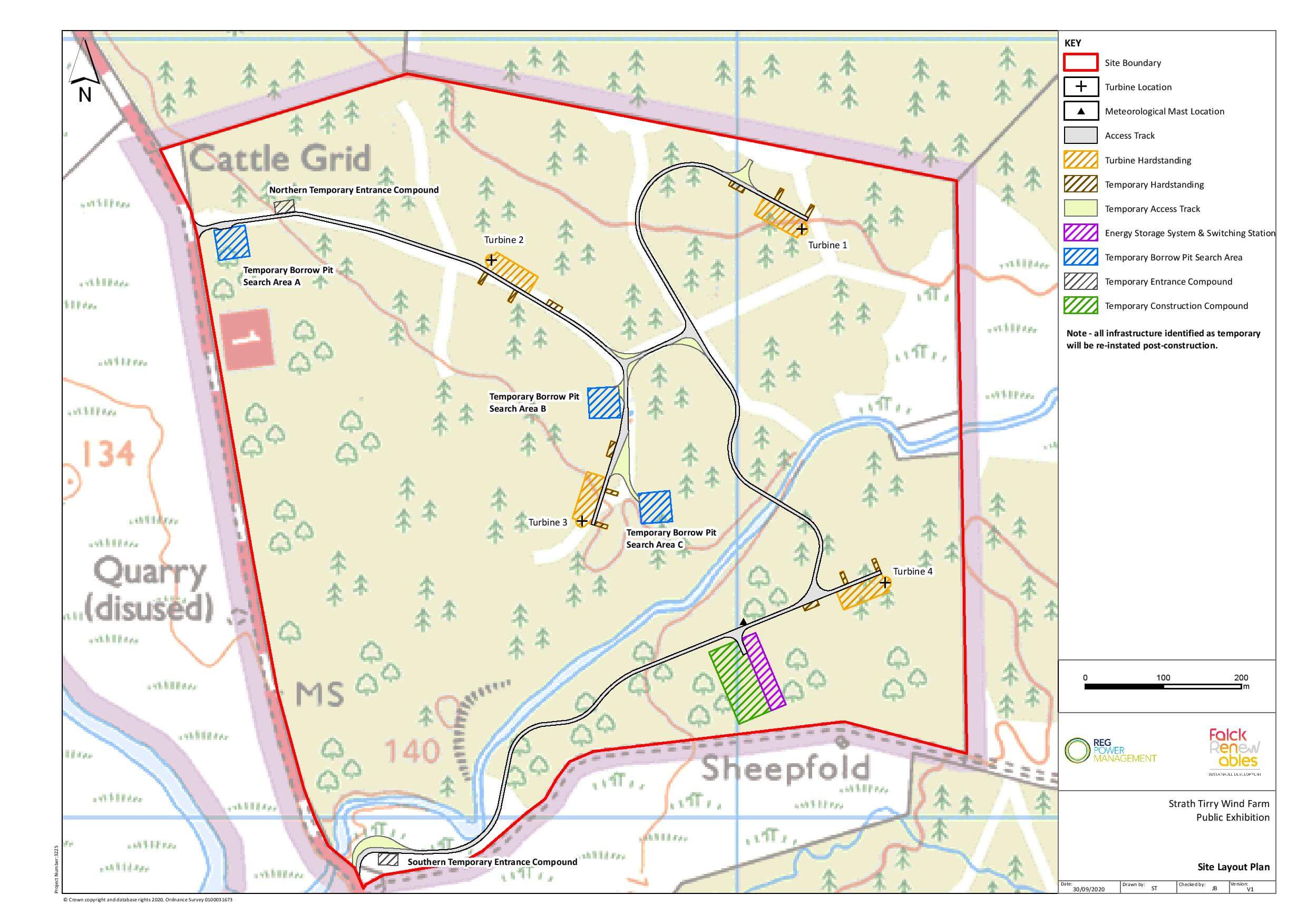
Proposed Development
- Wind farm and energy storage with an output of over 20MW
- 4 Turbines with a tip height of up to 135m
- Turbine hardstandings and laydown areas
- Access tracks
- Watercourse crossings
- Temporary construction compounds
- Switching station and control room
- Borrow pit search areas
- 10m meteorological mast
- 30-year operational life
Access and Transport
Access to the site would be taken from a junction on the A836, located to the south of the Feith Osdail bridge. To minimise construction traffic, access for abnormal loads associated with the turbines is expected to be from the port at Invergordon through to the site via the A9 and A839.
Turbine components will be delivered on specialist trailers. The longest, widest and heaviest will be escorted by the Police (at the developer’s expense) to ensure the highest standards of road safety. On site, loads will be assembled using a large crane and then bolted to the foundations. Delivery of turbine components is expected to last up to two months, if the project is consented.
Our project materials are available below and on The Highland Council Planning Portal.
Supplementary Environmental Information
Site Plans
- Site Plan 6.8D – Viewpoint 2a
- Site Plan 6.24A – Viewpoint 10a
- Site Plan 6.35 – Viewpoint 1
- Site Plan 6.36 – Viewpoint 2
- Site Plan 6.37 – Viewpoint 3
- Site Plan 6.38 – Viewpoint 4
- Site Plan 6.39 – Viewpoint 5
- Site Plan 6.40 – Viewpoint 6
- Site Plan 6.41 – Viewpoint 7
- Site Plan 6.42 – Viewpoint 8
- Site Plan 6.43 – Viewpoint 9
- Site Plan 6.44 – Viewpoint 10
- Site Plan 6.45 – Viewpoint 11
- Site Plan 6.46 – Viewpoint 12
- Site Plan 6.47 – Viewpoint 13
- Site Plan 6.48 – Viewpoint 14
- Site Plan 6.49 – Viewpoint 15
- Site Plan 6.50 – Viewpoint 16
- Site Plan 6.51 – Viewpoint 17
- Site Plan 6.52 – Viewpoint 18
- Site Plan 6.53 – Viewpoint 19
- Site Plan 6.54 – Viewpoint 20
Location Plans
- Location Plan 6.6A (EIA Report)
- Location Plan 6.6B (EIA Report)
- Location Plan 6.6C (EIA Report)
- Location Plan 6.7C (EIA Report)
- Location Plan 6.7D (EIA Report)
- Location Plan 11.3A – Viewpoint 11
Viewpoints
- Viewpoint 1 (Figure 6.15)
- Viewpoint 2 (Figure 6.16)
- Viewpoint 3 (Figure 6.17)
- Viewpoint 3a – A836 South of Dalmichy (Figure 2.8)
- Viewpoint 4 (Figure 6.18)
- Viewpoint 5 – A836 North of Rhian Bridge (Figure 2.9)
- Viewpoint 5a (Figure 6.19)
- Viewpoint 6 (Figure 6.20)
- Viewpoint 7 (Figure 6.21)
- Viewpoint 7a – Blarbuie (Figure 2.10)
- Viewpoint 8 (Figure 6.22)
- Viewpoint 9 (Figure 6.23)
- Viewpoint 10 – Saval (Figure 2.11)
- Viewpoint 11 (Figure 6.25)
- Viewpoint 12 (Figure 6.26)
- Viewpoint 13 (Figure 6.27)
- Viewpoint 14 (Figure 6.28)
- Viewpoint 15 (Figure 6.29)
- Viewpoint 16 (Figure 6.30)
- Viewpoint 17 (Figure 6.31)
- Viewpoint 18 (Figure 6.32)
- Viewpoint 19 (Figure 6.33)
- Viewpoint 20 (Figure 6.34)
General Plans
- General Plan – Wireline Drawing Viewpoint 1 (11.3B)
- General Plan – Wireline Drawing Viewpoint 1 (11.3C)
- General Plan – Wireline Drawing Viewpoint 1 (11.3D)
- General Plan – Wireline Drawing Viewpoint 1 (11.3E)
- General Plan – Wireline Drawing Viewpoint 1 (11.3J)
- General Plan – Wireline Drawing Viewpoint 2 (11.4B)
- General Plan – Wireline Drawing Viewpoint 2 (11.4C)
- General Plan – Wireline Drawing Viewpoint 2 (11.4E)
- General Plan – Wireline Drawing Viewpoint 3 (11.5B)
- General Plan – Wireline Drawing Viewpoint 3 (11.5C)
- General Plan – Wireline Drawing Viewpoint 3 (11.5A)
- General Plan – Wireline Drawing Viewpoint 3 (11.5D)
- General Plan – Wireline Drawing Viewpoint 4 (11.6E)
- General Plan – Wireline Drawing Viewpoint 4 (11.6D)
- General Plan – Wireline Drawing Viewpoint 4 (11.6C)
- General Plan – Wireline Drawing Viewpoint 4 (11.6B)
- General Plan – Wireline Drawing Viewpoint 5 (11.7C)
- General Plan – Wireline Drawing Viewpoint 5 (11.7D)
- General Plan – Wireline Drawing Viewpoint 5 (11.7E)
- General Plan – Wireline Drawing Viewpoint 5 (11.7B)
- General Plan – Wireline Drawing Viewpoint 6 (11.8E)
- General Plan – Wireline Drawing Viewpoint 6 (11.8B)
- General Plan – Wireline Drawing Viewpoint 6 (11.8C)
- General Plan – Wireline Drawing Viewpoint 6 (11.8D)
- General Plan – Wireline Drawing Viewpoint 6 (11.8D)
- General Plan – Wireline Drawing Viewpoint 7 (11.9B)
- General Plan – Wireline Drawing Viewpoint 7 (11.9D)
- General Plan – Wireline Drawing Viewpoint 7 (11.9E)
- General Plan – Wireline Drawing Viewpoint 7 (11.9C)
- General Plan – Wireline Drawing Viewpoint 8 (11.10D)
- General Plan – Wireline Drawing Viewpoint 8 (11.10E)
- General Plan – Wireline Drawing Viewpoint 8 (11.10C)
- General Plan – Wireline Drawing Viewpoint 8 (11.10B)
- General Plan – Wireline Drawing Viewpoint 8 (11.10 XXX)
- General Plan – Wireline Drawing Viewpoint 8 (11.10B)
- General Plan – VFR 250k Chart Extract (Figure 14.1)
- General Plan – VFR 500k Chart Extract (Figure 14.2)
- General Plan – Telecommunication Link Location (Figure 15.1)
- General Plan – Existing Forestry (Figure 16.1)
- General Plan – Area to be Felled (Figure 16.2)
- General Plan – Environmental Constraints and Opportunities Outwith Site Boundary (Figure 2.1)
- General Plan – Tourism and Recreation Receptors (Figure 13.2)
- General Plan – Typical Switching Station, Control Building and Energy Storage System (Figure 3.8)
- General Plan – Landform (Figure 6.2)
- General Plan – Landscape Planning Designations with Blade Tip ZTV (20km) (Figure 6.10)
- General Plan – Wild Land with Blade Tip ZTV (Figure 6.11)
- General Plan – Principal Visual Receptors with Blade tip ZTV (20km) (Figure 6.12B)
- General Plan – Cumulative Wind Farms (60km) (Figure 6.13A)
- General Plan – Cumulative Wind Farms (40km) (Figure 6.13B)
- General Plan – Cumulative ZTV – Achany (Figure 6.14A)
- General Plan – Cumulative ZTV – Beinn Tharsuinn Plus Extension (Figure 6.14B)
- General Plan – Cumulative ZTV – Braemore (Figure 6.14C)
- General Plan – Cumulative ZTV – Coire na Cloiche (Figure 6.14D)
- General Plan – Cumulative ZTV – Creag Riabhach (Figure 6.14E)
- General Plan – Cumulative ZTV – Gordonbush Plus Extension (Figure 6.14F)
- General Plan – Cumulative ZTV – Kilbraur Plus Extension (Figure 6.14G)
- General Plan – Cumulative ZTV – Lairg Estate (Figure 6.14H)
- General Plan – Cumulative ZTV – Lairg II (Figure 6.14I)
- General Plan – Cumulative ZTV – Meall Buidhe (figure 6.14J)
- General Plan – Cumulative ZTV – Rosehall (Figure 6.14L)
- General Plan – Cumulative ZTV – South Kilbruar (Figure 6.14L)
- General Plan – Cumulative ZTV – Strathrory (Figure 6.14M)
- General Plan – Cumulative ZTV – Strathy South (Figure 6.14N)
- General Plan – Cumulative ZTV – Strathy South (Resubmission) (Figure 6.14O)
- General Plan – Designated Sites (Figure 7.3)
- General Plan – Waterfowl Flights (Figure 7.4A)
- General Plan – Wader Flights (Figure 7.4B)
- General Plan – Raptor and Corvid Flights (Figure 7.4C)
- General Plan – Diver Survey Results (Figure 7.5)
- General Plan – Designated Sites (Figure 8.1)
- General Plan – NVC Habitat Types (Figure 8.2)
- General Plan – Groundwater Dependant Terrestrial Ecosystems (GWDTE) (Figure 8.3)
- General Plan – Landscape Character (40km) (Figure 6.3A)
- General Plan – Landscape Character (20km) (Figure 6.3B)
- General Plan – Landscape Planning Designations (40km) (Figure 6.4A)
- General Plan – Landscape Planning Designations (20km) (Figure 6.4B)
- General Plan – Wild Land (Figure 6.5)
- General Plan – Blade Tip ZTV with Viewpoints (40km) (Figure 6.7A)
- General Plan – Blade Tip ZTV with Viewpoints (20km) (Figure 6.7B)
- General Plan – Landscape Character with Blade Tip ZTV (20km)
- General Plan – Study Areas (Figure 7.1)
- General Plan – Bedrock Geology (Figure 9.2)
- General Plan – Surface Geology (Figure 9.3)
- General Plan – Peat Depth Records and Contours (Figure 9.4)
- General Plan – Potential GWDTE (Figure 9.5)
- General Plan – Watercourses Crossings (Figure 9.6)
- General Plan – Watercourse Crossing Indicative Bottomless Arch Crossing (Figure 3.5A)
- General Plan – Watercourse Crossing Indicative Single Span Crossing (Figure 3.5C)
- General Plan – Freshwater Invertebrate and Fish Sampling Locations
- General Plan – Environmental Constraints and Opportunities within the site Boundary (Figure 2.2)
- General Plan – Noise Monitoring Position, Noise Sensitive Receptors and Noise Continued (Figure 10.1)
- General Plan – Cultural Heritage Inner Study Area (Figure 11.1)
- General Plan – Cultural Heritage Outer Study Area (Figure 11.2)
- General Plan – Study Area and Traffic Survey Locations (Figure 12.1)
Location Plans
- Location/Site Layout Plan
- Viewpoint Location Plan
- Location Plan (Figure 1.1)
- Location Plan – View Point 2 (11.4D)
- Location Plan – View Point 3 (11.5E)
- Location Plan – Viewpoint 5 (11.7A)
- Location Plan – Viewpoint 7 (11.9A)
- Location Plan – Viewpoint 8 (11.10A)
- Location Plan – Viewpoint (11.8A)
- Location Plan – Site Location within the Spatial Framework (Figure 5.1)
- Location Plan – Site Location and Study Area (Figure 6.1)
Chapters
- Chapter 1 – Introduction
- Chapter 2 – Site Selection and Design Iteration
- Chapter 3 – Project Description
- Chapter 4 – Approach to EIA
- Chapter 5 – Planning and Energy Policy
- Chapter 6 – Landscape and Visual
- Chapter 7 – Ornithology
- Chapter 8 – Ecology
- Chapter 9 – Geology, Peat, Hydrology and Hydrogeology
- Chapter 10 – Noise
- Chapter 11 – Cultural Heritage
- Chapter 12 – Traffic and Transport
- Chapter 13 – Socio-Economic and Tourism
- Chapter 14 – Aviation
- Chapter 15 – Telecommunication
- Chapter 16 – Forestry
- Chapter 17 – Draft Scheme of Mitigation
- Chapter 18 – Summary of Residual Effects
Site Layout Plans
- Site Layout Plan – Paths and Access (Figure 13.3)
- Site Layout Plan – Turbine Layouts A + B (Figure 2.3)
- Site Layout Plan – Turbine Layouts B, C + D (Figure 2.4)
- Site layout Plan – Turbine Layouts D, E + F (Figure 2.5)
- Site Layout Plan – Infrastructure Layouts 1 + 2 (Figure 2.6)
- Site Layout Plan – Infrastructure Layouts 3 + 4
- Site Layout Plan – Field Survey Locations (Figure 7.2)
- Site Layout Plan – 2017 Phase 1 Habitat Survey (Figure 8.4)
- Site Layout Plan – Bat Detector Locations (Figure 8.6)
- Site Layout Plan – Hydrology Study Area and Watercourses (Figure 9.1)
- Site Layout Plan (Figure 1.2)
Section Plans
- Section Plan – Typical Access Track Cross-Section (Figure 3.3)
- Section Plan – Typical Switching Station and Control Building Plan and Elevations (Figure 3.6)
- Section Plan – Typical Energy Storage System Plan + Elevations (Figure 3.7)
- Section Plan – Typical Meteorological Mast Elevation (Figure 3.9)
- Section Plan – Typical Construction Compound (Figure 3.10)
Visual Information
- Visual Information – Baseline Photograph Viewpoint (11.3F)
- Visual Information – Baseline Photograph Viewpoint 1 (11.3I)
- Visual Information – Baseline Photograph Viewpoint 1 (11.3G)
- Visual Information – Baseline Photograph Viewpoint 1 (11.3H)
- Visual Information – Photomontage Viewpoint 1 (11.3K)
- Visual Information – Location Plan Viewpoint 2 (11.4A)
Further Supporting Information
- The Planning Statement
- (file too large to be linked to this space: but can be found on this link)
- 2018 EIA Scoping Report
- (file too large to be linked to this space: but can be found on this link)
- 2018 EIA Scoping Response
- (file too large to be linked to this space: but can be found on this link)
- EIA Non-Technical Summary
- (file too large to be linked to this space: but can be found on this link)
- Design and Access Statement
- EIAR Contents
- A836 Access Junction Traffic Management Plan
- Elevations – Typical Wind Turbine Foundation (Figure 3.1)
- Foundation Plan – Typical Turbine Foundation (Figure 3.2)
- Drainage – Typical Drainage Design (Figure 3.4)
- Access Layout Plan – AIL Access Route (Figure 12.2)
Appendices
- Appendix 3.1 – Outline Drainage Strategy
- Appendix 3.2 – CEMP
- Appendix 3.3 – Carbon Calculator
- Appendix 4.3 – Cross Reference of EIA Scoping Opinion in the EIA Report
- Appendix 4.4 – Additional EIA Consultation Responses
- Appendix 4.6 – Shadow Flicker
- Appendix 4.6a – Figure 1 Shadow Flicker Study Area
- Appendix 4.7 – Major Accidents and Disasters
- Appendix 4.8 – Proposal of Application Notice
- Appendix 6.1 – LVIA Methodology
- Appendix 6.2A – WLA 34 Figure 1A REAY-Cassley WLA
- Appendix 6.2A – WLA 34 Figure 2A REAY-Cassley WLA with Hub Height ZTV
- Appendix 6.2A – Figure 3A REAY-Cassley WLA with JENKS Wildness Classes
- Appendix 6.2A – Figure 4A REAY_Cassley with Jenks Wildness Classes and Blade Tip Z
- Appendix 6.2A – Figure 5A REAY-Cassley WLA with Operational Turbine Cumulative ZTV
- Appendix 6.2A – Figure 6A REAY-Cassley WLA with Operational and Consented Turbine CU
- Appendix 6.2A – Assessment of Effects on Wild Land Area 34
- Appendix 6.2B – Figure 1B Ben Kilbreck-Armine WLA with Blade Tip ZTV
- Appendix 6.2B – Figure 2B Ben Kilbreck-Armine WLA with Hub Height ZTV
- Appendix 6.2B – Figure 3B Ben Kilbreck-Armine WLA with JENKS Wildness Classes
- Appendix 6.2B – Figure 4B Ben Kilbreck-Armine WLA with JENKS Wildness Classes
- Appendix 6.2B – Figure 5B Ben Kilbreck-Armine WLA with Operational Turbine Cumulat
- Appendix 6.2B – Figure 6B Ben Kilbreck-Armine WLA with Operational and Consented Turbine
- Appendix 6.2B – Assessment of Effects on Wild Land Area 35
- Appendix 6.2C – Figure 1C Foinaven – Ben Hee WLA with Blade Tip ZTV
- Appendix 6.2C – Figure 2C Foinaven – Ben Hee WLA with Hub Height ZTV
- Appendix 6.2C – Figure 3C Foinaven – Ben Hee WLA with Creag Riabhach Cumulative ZTV
- Appendix 6.2C – Assessment of Effect on Wild Land Area 37
- Appendix 6.3 – Figure 2A to 2E
- Appendix 6.3a – Residential Visual Amenity Assessment
- Appendix 7.2 – Habitats Regulations Appraisal
- Appendix 8.1 – Methodology and Results for Ecological Impact Assessment
- (file too large to be linked to this space: but can be found on this link)
- Appendix 8.2 – Photographic Log
- Appendix 8.3 – Wildcat Survey
- Appendix 8.5 – Fish Habitat and Population Assessment
- Appendix 8.6 – Deer Report
- Appendix 8.7 – Outline Habitat Management Plan
- Appendix 9.1 – Peat Slide Risk Assessment
- Appendix 9.2 – Outline Peat Management Plan
- Appendix 9.3 – Watercourse Crossing Schedule
- Appendix 9.1 – Geomorphology (Figure 1)
- Appendix 9.1 – Peat Survey and Sampling Locations (Figure 2)
- Appendix 9.1 – Peat Depth Records and Contour (Figure 3)
- Appendix 9.1 – Slope Map (Figure 4)
- Appendix 10.1 – Calibration Certificates
- Appendix 10.2 – Noise Monitoring Position
- Appendix 10.3 – Noise Charts
- Appendix 10.4 – Turbine Noise Source Terms Vestas 117
- Appendix 11.1 – Heritage Assets within the Inner Study Area
- Appendix 11.2 – Designated Heritage Assets
- Appendix 11.3 – Designated Heritage Assets Beyond Study Area
- Appendix 16.1 – Photographic Records of Forestry 17 Sept 2020
Annexes